Tail Gas Scrubber
Tail Gas Scrubber
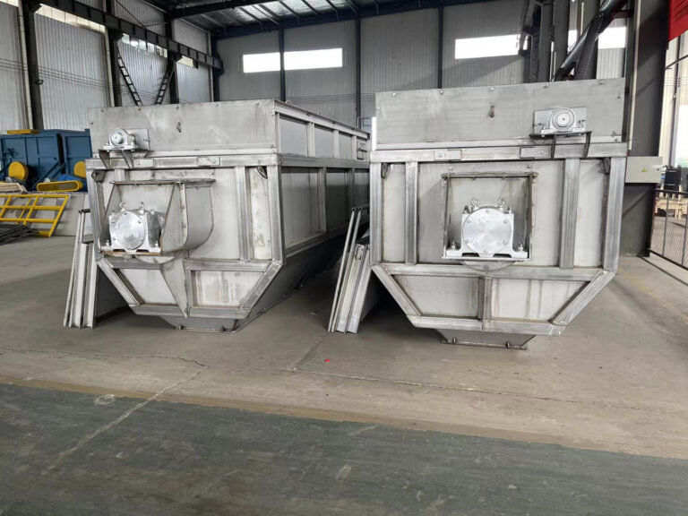
Fiberglass reinforced plastic acid mist purification tower for corrosive gases (such as acid, alkaline waste gas) management, the liquid absorption method to manage the waste gas. The process and products have a simple structure, low energy consumption, high purification efficiency and a wide range of characteristics, acid waste gas introduced into the purification tower by the air duct, through the packing layer, the waste gas and alkali (acid) for gas-liquid two-phase full contact absorption and neutralization reaction, acid waste gas after purification, and then by the mist elimination plate dewatering mist removed from the blower discharged into the atmosphere.

Advantages of Tail Gas Scrubber
- Energy Saving: No packing and gas-liquid exchange tray, low system resistance, and reduced fan power.
- Easy to manage: It can be equipped with a gas online analyzer, a PH control meter differential pressure transmitter, a pressure sensor, a solenoid valve inverter, and other control systems, as well as a digital display.
- Long exchange time: Because this tower adopts atomized upward spraying, when the liquid and gas exchange, it will be exchanged through the upper and lower two upward strokes, which prolongs the exchange time.
- Specialized Atomizer: Atomizer nozzle completely atomizes the liquid, large gas-liquid exchange area, complete absorption and purification, uniform arrangement of washing nozzles, and purification efficiency of 98-99%.
Tail Gas Scrubber Applicable Materials
Widely used in chemical, electronics, metallurgy, electroplating, machinery manufacturing and other industries in the process of emissions of acid, alkaline waste gas treatment.
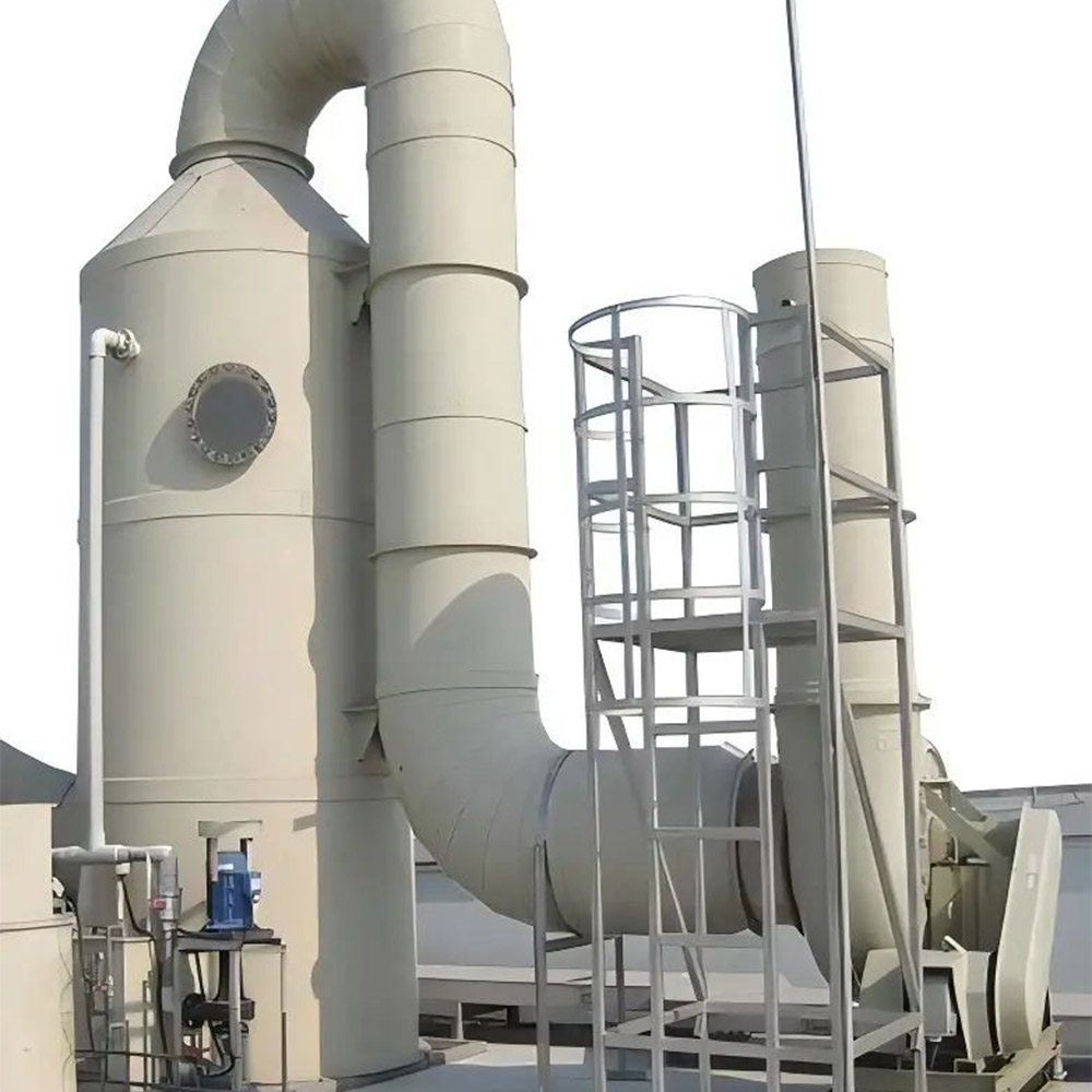
Tail Gas Scrubber Product Schematics

Model | Processing air volume | φ | φ1 | H1 | H | purification rate | Recommended Pumps |
TL-500 | 1200 | 500 | 200 | 1200 | 3500 | 98% | 5m3/h H=25m |
TL -600 | 2000 | 600 | 200 | 1200 | 3500 | 98% | 5m3/h H=25m |
TL -700 | 3000 | 700 | 300 | 1400 | 4000 | 98% | 7.5m3/h H=25m |
TL -800 | 4000 | 800 | 300 | 1400 | 4000 | 98% | 10m3/h H=25m |
TL -1000 | 5000 | 1000 | 400 | 1400 | 4500 | 98% | 15m3/h H=25m |
TL -1200 | 6000 | 1200 | 450 | 1600 | 4500 | 98% | 15m3/h H=25m |
TL -1400 | 8000 | 1400 | 500 | 1600 | 5000 | 98% | 20m3/h H=25m |
TL -1600 | 10000 | 1600 | 600 | 1800 | 5000 | 98% | 25m3/h H=25m |
TL -1800 | 15000 | 1800 | 700 | 2000 | 5500 | 98% | 35m3/h H=25m |
TL -2000 | 20000 | 2000 | 800 | 2200 | 5500 | 98% | 50m3/h H=25m |
TL -2200 | 25000 | 2200 | 1000 | 2500 | 6000 | 98% | 60m3/h H=25m |
TL -2500 | 30000 | 2500 | 1000 | 2500 | 6000 | 95% | 75m3/h H=25m |
TL -2800 | 40000 | 2800 | 1100 | 3000 | 7000 | 95% | 80m3/h H=25m |
TL -3000 | 45000 | 2800 | 1100 | 3200 | 7500 | 95% | 900m3/h H=25m |
What Else Does TONGLI offer?
Our Products
We are the industry heads and produce the most reliable and trendy fertilizer production line solution you are looking for.
NPK compound fertilizer steam granulation solution
Suitable for making compound fertilizers, organic fertilizers and mixed fertilizers with diversified formulas with large output
NPK roller extrusion granulation method production
Save energy consumption, flexible output, small investment
High tower prilling method npk fertilizer production
Large investment, large output, suitable for making high-nitrogen NPK compound fertilizer
BB fertilizer blending line
Small investment, flexible output, and can mix a variety of formulas
The only place where you’ll get the perfect solution for fertilizer industry needs.
Frequently Asked Questions
1. Installation: After the machine arrives at the factory, it will be installed in conjunction with the process, indicating the elevation and horizontal position, tilted installation, generally tilted at 2-5 degrees (which can be adjusted to make the user’s needs), and the machine bracket and transmission frame even ground angle holes, which can be mounted on rolled condensed soil.
① machinery each base and the foundation between the pad into the deed-shaped mat board thickness should not be greater than 30-35mm;
② the height of the base with the deed-shaped pad to adjust the height of the base to make the base 5 degrees of inclination;
③ After each base is adjusted properly, put the cylinder on the support and adjust the carrier wheel;
④ Install the drive part of the film wrapping machine;
⑤ Be sure that the bracket wheel, transmission device and cylinder are properly adjusted and start pouring cement, and after 8-10 days, start the no-load test run after the cement is solidified;
⑥ Method of adjusting the position of the machine body:
a. On the full length of the left and right sides of the machine body, install two parallel steel wires with a diameter of 0.5-1mm and check the level of the wires with a level meter;
b.Lower two phase hammers tangent to the rolling circle from each rolling circle down the sides of the dryer;
c.Measure the distance from the steel wire to the wire drop to detect the body in the horizontal position;
d. Measure the relative vertical elevation of the two rolling circles to check the position of the machine body in the vertical plane;
e. Use the method of moving the electric torque wheel to adjust the measurement of the two articles c and d, so that the machine body is in the correct position;
2. No-load test run:
1). Uninterrupted no-load for 8 hours, the temperature of each bearing should rise smoothly, and the temperature of the bearing should not be higher than 50 degrees Celsius at the termination of the test run;
2). The noise of gears should be average and should not be high or low;
3). After the test run, the bearings shall be observed without serious wear and abrasion.
A.Starting the machine
1. The following preparations should be made before starting the film wrapping machine;
a. Check and adjust the powder feeding device and protection equipment;
b. All bearings and lubricating devices of friction surfaces should have appropriate quantity of grease;
2. It is forbidden to start the film wrapping machine without checking the film wrapping machine and auxiliary mechanical equipment;
3. The steps to start the film wrapping machine are as follows:
a. Start the motor of the film wrapping machine.
b. Start the feeding and discharging conveying equipment.
B. Stopping
1. The steps to stop the film wrapper are as follows:
A. Stop adding raw material to the wrapper;
B. Turn off the drive motor of the wrapping machine;
C. Stop the equipment for transporting granular materials;
1. Dry grease should be smeared at the gears before starting the machine;
2. Dry grease to be smeared on the surface of rolling belt once in 7 days;
3. Bearing housing to be hit or renewed with new dry grease every three months;
4. Add gear oil once before the reducer is used and replace it every four months thereafter;
Pinion gear is worn, install pinion gear upside down, if both sides are worn, new gear is needed.
The intermediate connection between the large gear and the cylinder is damaged, adjust the connection and make appropriate treatment if necessary.
Clamping roller belt to the side of a concave joint
Clamp the belt to the concave joints with pads or wedges, but beware of over-clamping, which can lead to accidents, but uneven tensioning can cause the machine to jump and vibrate.
Wheel wear Refurbish or replace the wheel according to the degree of wear
Block wheel wear Repair, move, or replace with new block wheel depending on degree of wear
Simple body vibration

